I have a strong foundation as an engineer through my projects and my coursework, and I am eager to learn more. I thrive working in team environments, and I am proud of my work ethic and integrity. I am not intimidated by challenges; I see difficult situations as opportunities for growth and learning. I value excellence in my work. I pride myself in being honest, dependable, and a team asset.
I recently graduated from Oregon State University with a Bachelor of Science in mechanical engineering and a minor in aerospace engineering.
Throughout my education I developed a passion for engineering and science. Learning the fundamentals of orbital mechanics and propulsion systems inspired my desire to participate in the future of space exploration.
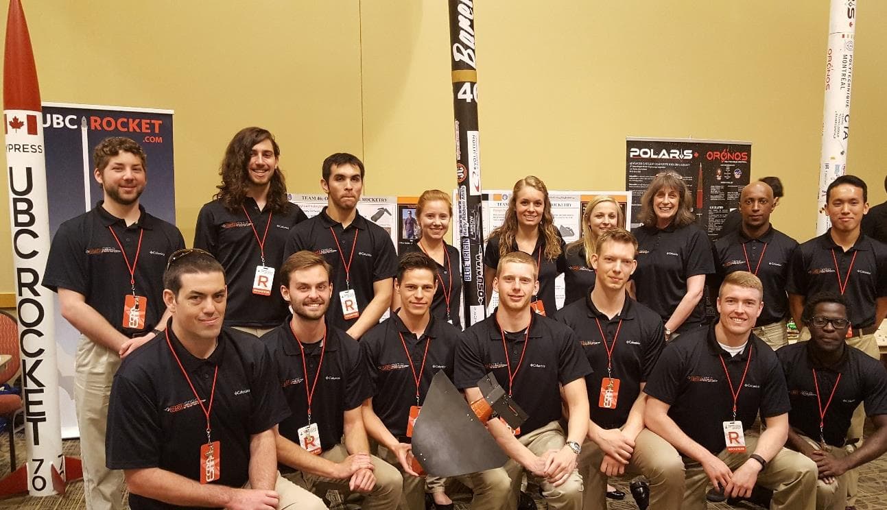
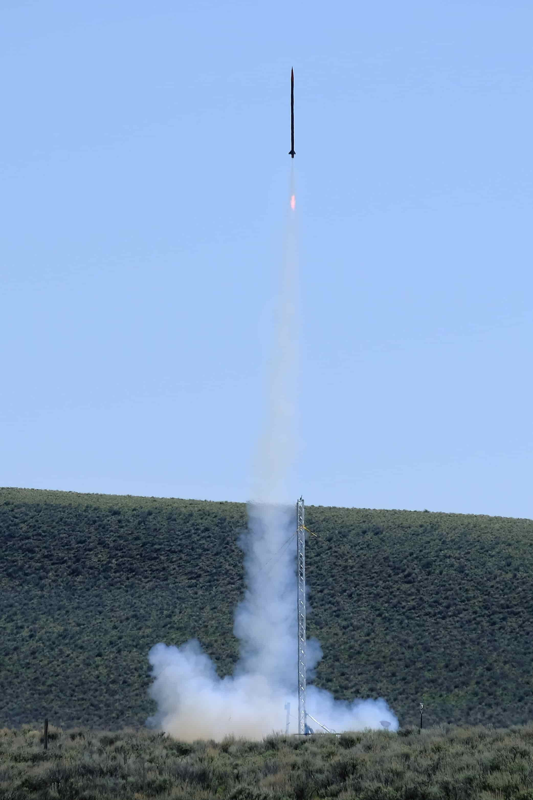
As a part of the Oregon State University 30,000 ft. rocket team, I designed, built, and tested a rocket deployed glider. The team consisted of twelve mechanical, two electrical engineers, and three computer scientists.
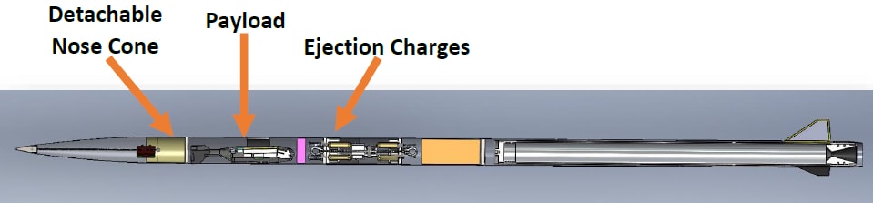
Specifically, I was on the Payload sub-team, which was responsible for the scientific payload carried inside the rocket. The payload was a fixed wing autonomously guided glider. Our goal was for the glider to eject from the rocket at apogee, to free fall to a predetermined altitude where the wing would deploy and the guidance system control the glider's descent to a landing site. Our motivation for creating this payload was to prototype a high altitude UAV with no onboard propulsion. The glider was equipped with a CO2 sensor and video camera that would be analyzed upon recovery.
Two recovery systems were used: a primary and a secondary. The primary recovery system was the wing and tail which provided lift and guided it to the landing site. The secondary recovery system was a parachute that deployed at a 700 ft. Both recovery systems were entirely student designed, manufactured, and tested.
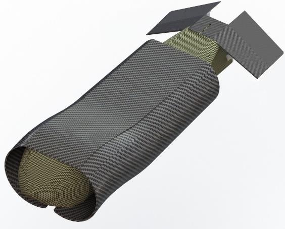
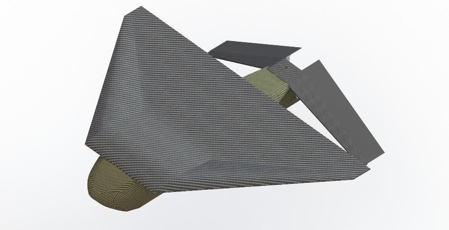
A carbon fiber load stiffened wing was used as the primary lifting body for the glider. A load stiffened wing is capable of being rolled under pressure and automatically stiffened into a flight configuration when released. The wing was made out of three plies of T-800 carbon fiber weave with a [45°/-45°/45°] layup schedule, providing the ability for it to roll without snapping so it can be placed in the 4.5 inch rocket tube.
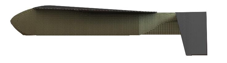
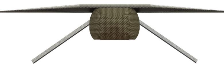
The tail section of the payload was designed to give the glider control authority and stability during its flight while still being able to fit inside of the rocket. Originally a traditional tail design was selected for simplicity but this did not provide the surface area needed to properly control the glider. The solution was to use an inverted V-tail. It was possible fit a much larger control area inside the rocket, since the tail can roll similarly to the wing. Additionally, the inverted “V” design only had two control surfaces which reduced the number of required components.
The fuselage was made entirely out of Kevlar composite and was designed to be small enough to fit inside the rocket with the wing rolled around it and large enough to house all of the required components. The included components were a GoPro camera, 7.4 V Li-Po battery (3x), 9 V battery (3x), Stratologger (2x), 868 MHz long range radio, Pixhawk autopilot (flight controller), power module, CO2 sensor, GPS, servo motor (2x), parachute chamber, Cypres cutter (wing release mechanism), and a Walston tracker (redundant tracker). The components were secured and organized inside the fuselage with a 3D printed sled. The glider weighed approximately 3.8 lbs.
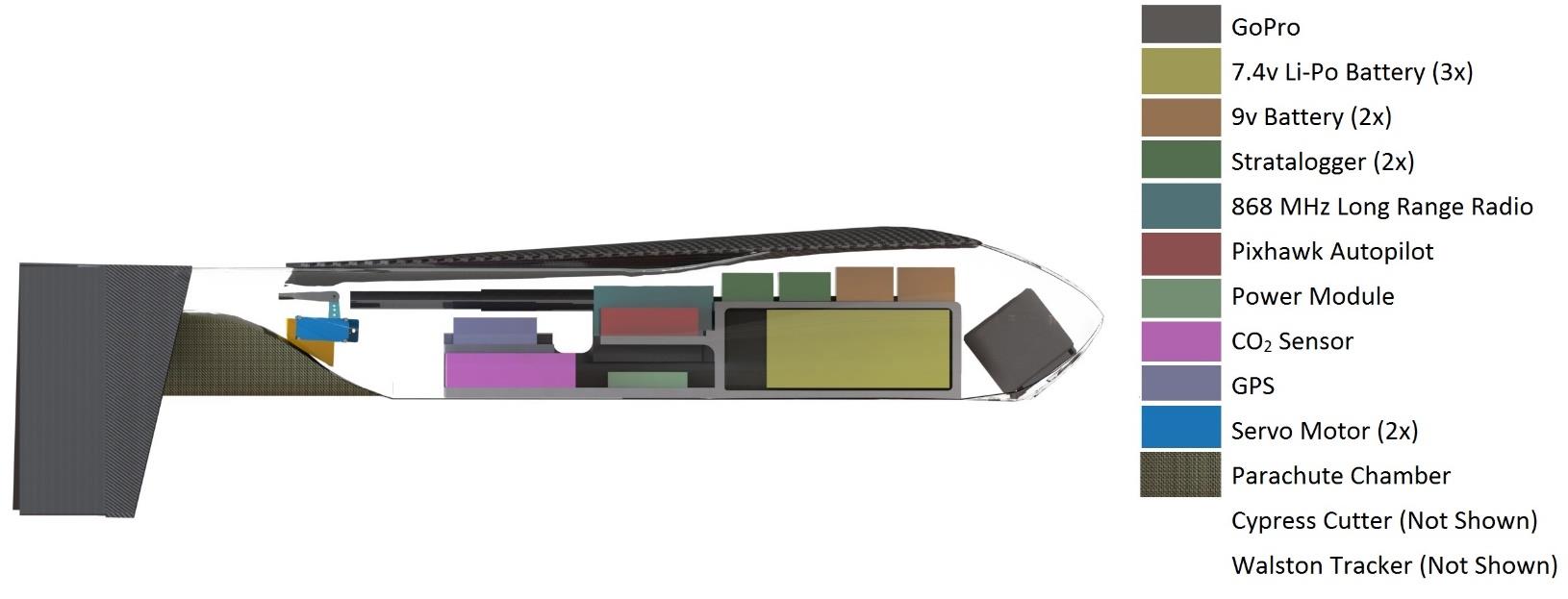
As a necessary recovery redundancy, a deployable parachute recovery system was added to the Payload. The parachute chamber is housed at the rear of the glider under the tail section. Using a black powder charge, it deployed at 700 ft, and slowed the payload to 30 ft/s, ensuring the payload landed safely with all components intact.
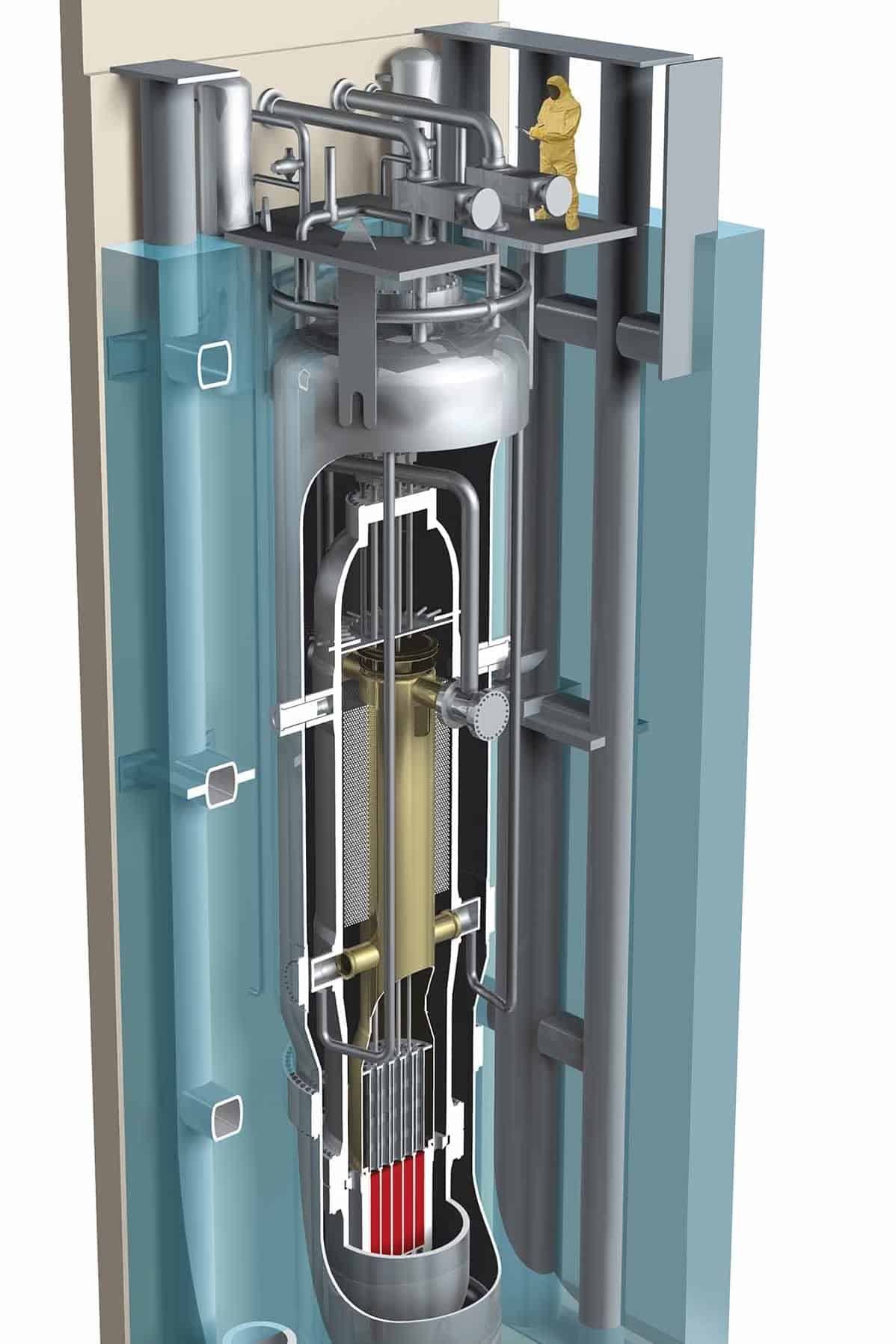
At my year long internship with NuScale Power I worked on a variety of projects which required an extensive use of SolidWorks, ANSYS, and MathCad. NuScale is an innovative nuclear power design company working on small, modular reactors.
One of my projects was to analyze stresses in pressure vessels and the vessel's outlets. For the analysis I used Mathcad to calculate the principal stresses for varying combinations of the following loads: seismic, thermal, weight, and pressure. Then I spot checked my results using ANSYS to ensure that the vessels and outlets meet ASME standards. I created simplified models using SolidWorks to allow ANSYS to solve more efficiently. This reduced the complexity in generating a mesh in ANSYS as well as reducing the computation time. Working with a team on complex problems at NuScale was a great experience for me to apply what I have learned in school to the nuclear industry.
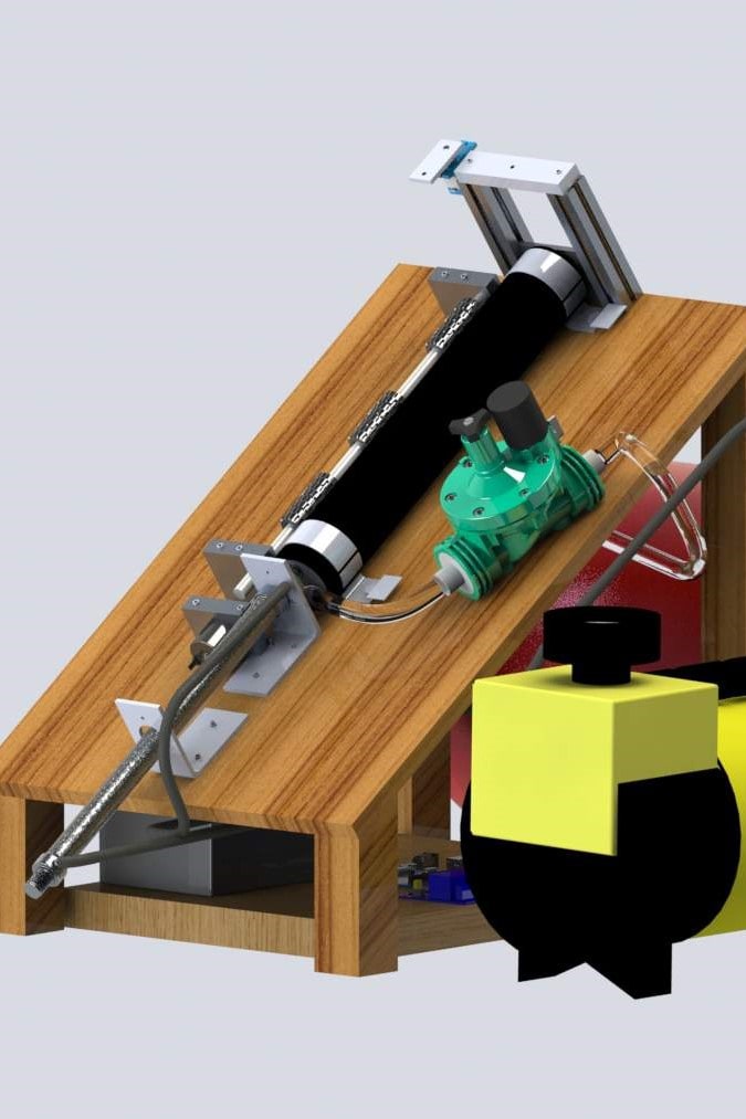
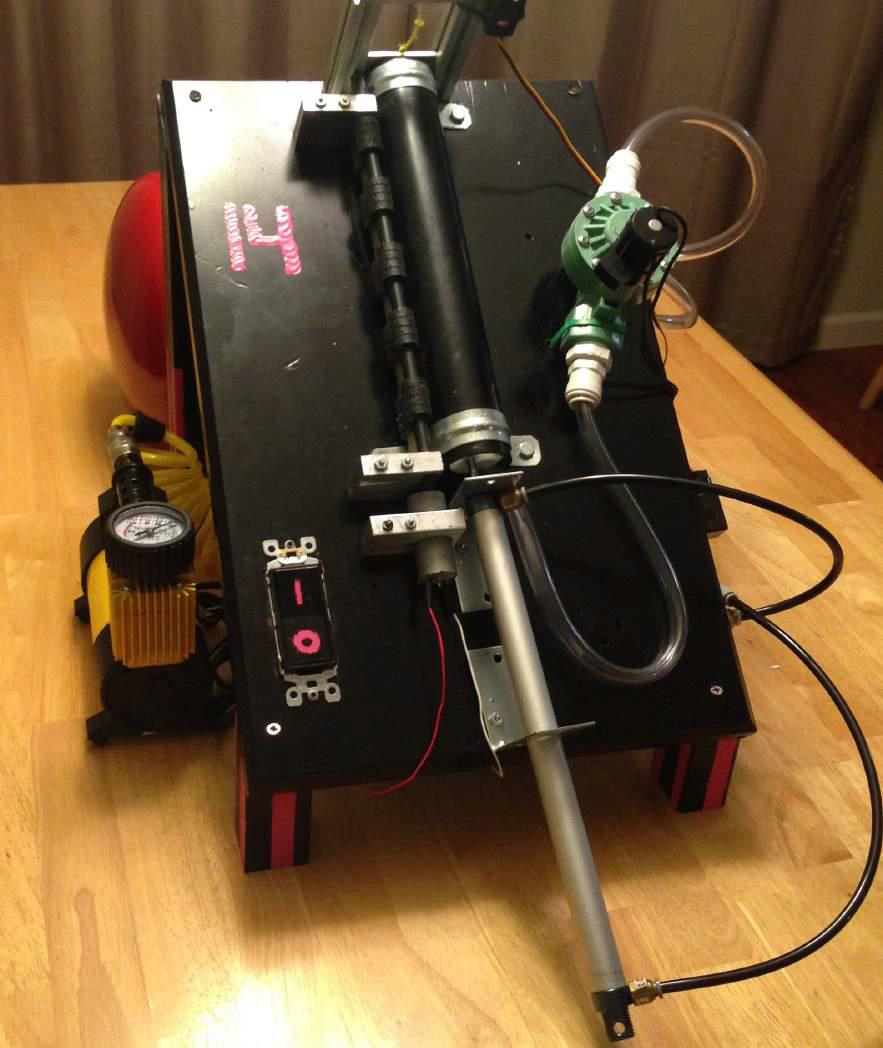
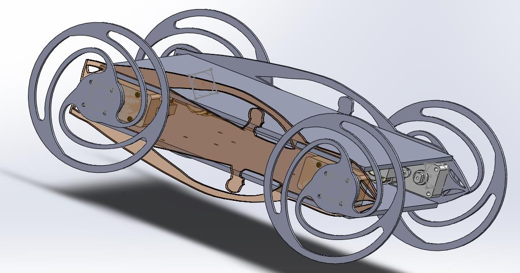
As a part of a junior level design class we had a competition to build a paper launcher capable of launching paper into a hole 3 meters away. I worked with 3 other mechanical engineers to develop what you see in the above rendering.
The process to launch a piece of paper from our device is outlined below:
The components used included a five-gallon air tank to power a solenoid and provide a burst of air to launch the paper, a paper feeder system, an Arduino, and a 12V battery to power the air compressor.
The final design resulted in a compact, efficient and easily manufactured device that was capable of launching three meters. In the process we performed a variety of tests and iterated our design. Skills learned and refined during this project are the extensive design processes, the importance of time management and scheduling, and the forethought of designing a device that is within the scope of our abilities to manufacture in the allotted.
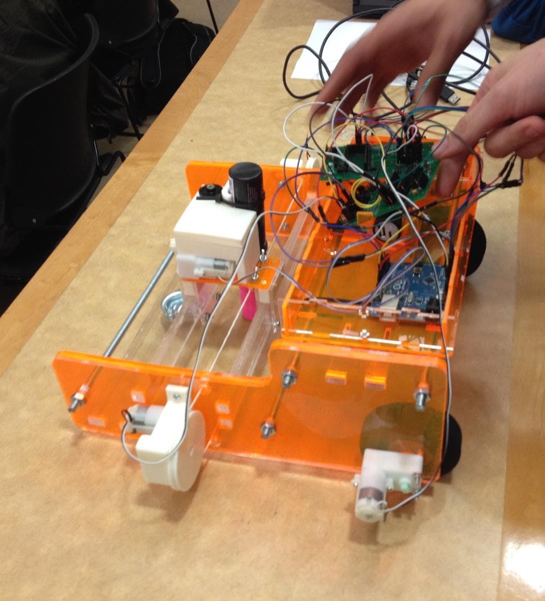
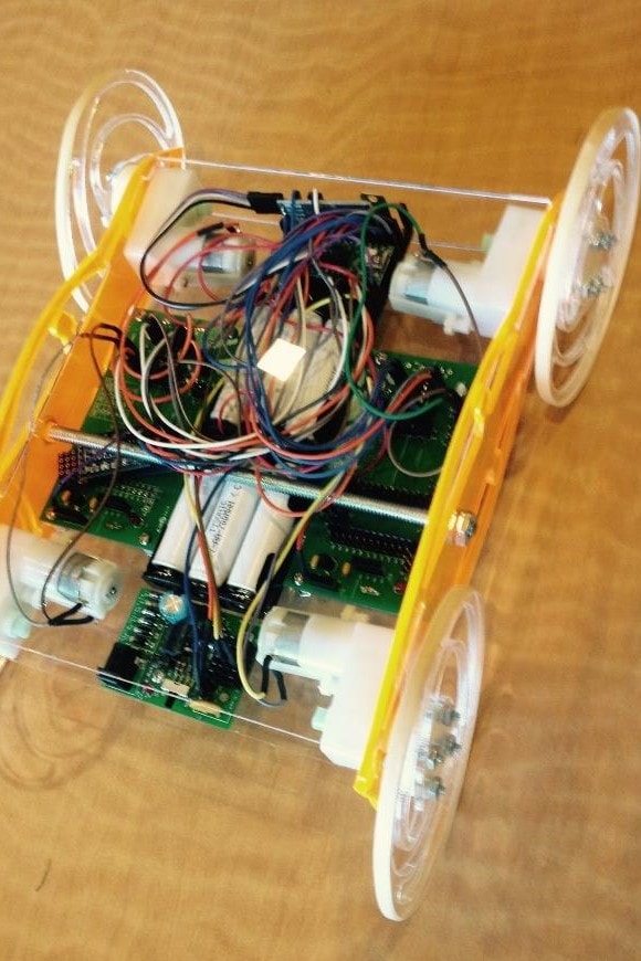
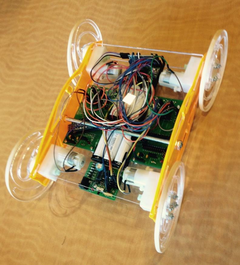
Oregon State University has a quarterly design competition called HWeekend. It is a 30 hour open ended engineering challenge where teams are given a variety of components and access to a laser cutter and 3D printer to build whatever they want. I participated in the event twice, and both times I worked in a team of 7 engineers.
The first time we built a smart phone app controlled car. The structure was made from this acrylic sheets and was designed to be able to drive on its belly or back. The wheels were designed to be light weight and impact absorbing. Shown below is the car we designed, built, and drove within 30 hours.
The second project that I worked on was an automated sidewalk chalk marker. It downloaded an image from the internet, transformed it into a field of 1’s and 0’s. Then it would take that field and recreate the image on a sidewalk using a liquid chalk marker. We finished building the device and developing the software for it within the 30 hour window, however we did not have the time to bridge the gap between the two to get a functioning prototype.